Guideline for Manual Call Point


MANUAL CALL POINT REFERENCE
Area Code Clause No Descriptions
Mounting Height NFPA 72 17.14.5  The operable part must be between 1.07 meter to 1.22 meter above the finished floor.
BS 5839-1:2025 20.2 Typically mounted at 1.4 meters (0.2m above or 0.3m below) allowing placement between 1.1 meter and 1.6 meter. For disabled access, heights may be lowered to 0.9 meter  to  1.2 meter.
IS 2189  6.3.8 Call points shall be fixed at a height of 1.4 meter above the surrounding floor level, at easily accessible, we illuminated and conspicuous positions, which are free of obstructions.
From Door Distance NFPA 72 17.15.9.6  pull stations are required to be located within 1.5 meters of each exit doorway on every floor, ensuring they are easily reachable during emergencies. 
NFPA 101  9.6.2.3  the manual fire alarm box shall be located within 1525 mm of exit doorways.
NFPA 101  9.6.2.4 Manual fire alarm boxes shall be mounted on both sides of grouped openings over 40 ft (12.2 meter) in width, and within 1525 mm of each side of the opening.
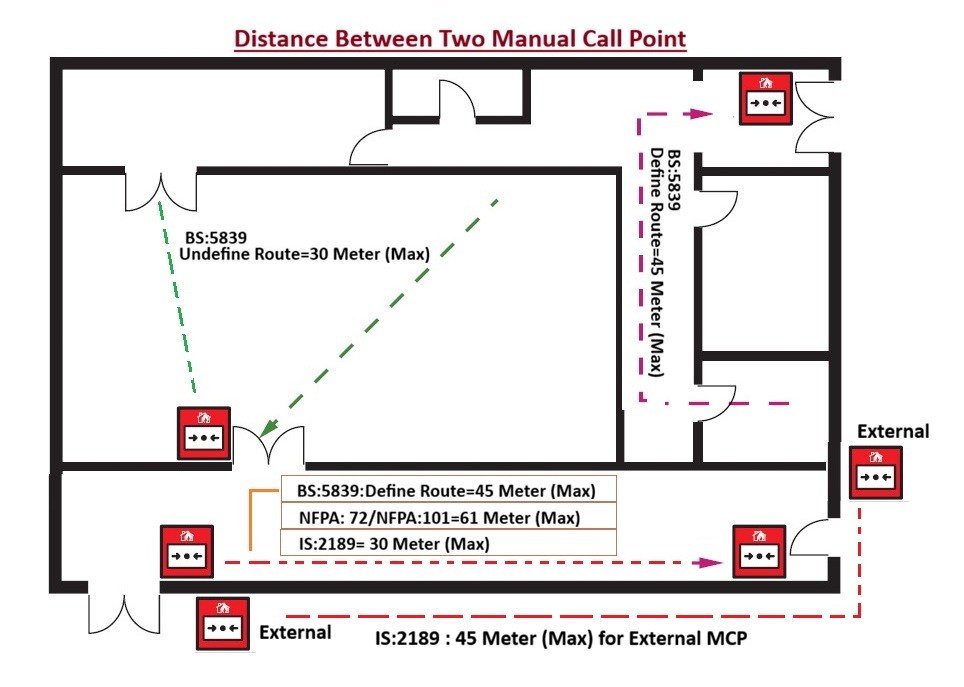
Travel Distance NFPA 101 9.6.2.5 No horizontal distance on that floor exceeding 200 ft (61 meter) shall need to be traversed to reach a manual fire alarm box.
BS 5839-1:2025  20.2 MCPs must be on escape routes and Distribution of MCPs should be such that no one need travel more than 45 meter in certain route (or 30 meter if layouts are uncertain). For disabled residents this should be adapted to within 25 meter to 16 Meter  of each other. For high-risk areas (e.g. kitchens or cellulose paint spraying) a MCP should be sited in close proximity.
NFPA 72 17.15.9.5 Additional manual fire alarm boxes shall be provided so that the travel distance to the nearest manual fire alarm box will not exceed 200 ft (61 meter), measured horizontally on the same floor.
IS 2189  6.3.8 Manual call points shall be so located that, to give an alarm, no person in the premises has to travel distance of more than 30 meter to reach them. When manual call points are also installed external to the building, the travel distance shall be 45 meter
IS 2189  6.3.8 Where necessary, the travel distance may require to be reduced to less than 30 meter, for example, where there is difficulty in free access within the risk or in potentially dangerous risks.
       
Location BS 5839-1:2025    Not placing MCPs at non-final exits or in unsupervised areas like shopping centers.
IS 2189  6.3.8 Manual call point shall be located preferably near entry to staircases at various levels.
NBC 2016  J-9.1.4 Manual call station(s) shall be provided at central location(s) on each platform (near emergency plunger) and at least two on the concourse,  on  each  sidewall. When  the concourse is in two halves, at least one manual call station shall be provided on each side.
BS 5839-1:2017  20.2 MCPs should be located on escape routes and, in particular, at all story exits and all exits to open air that lead to an ultimate place of safety (whether or not the exits are specifically designated as fire exits)
Staircase Landing  BS 5839-1:2017  20.2 MCPs should not be located on stairway landings, as persons travelling down the stairway might operate an MCP several floors below that on which a fire is located, resulting in evacuation of inappropriate areas.
Protecting Cover / Duct Proof BS 5839-1:2025    MCP may provide fitting covers or guards to prevent false alarms and damage.
 NFPA 72 17.14.7 Listed protective covers shall be permitted to be installed over single- or double-action manually actuated alarm initiating devices.
IS 2189  6.3.8 Manual call points shall be housed in dust pre of and moisture proof enclosure properly sealed with rubber lining. 
Recess Mounting IS 2189  6.3.8 Where the call points are not visible from the front as in the case of a long corridor, they shall be surface mounted or semi-recessed in order to present a side profile area of not less than 750 mm.
BS 5839-1:2017  20.2 MCPs may be flush-mounted in locations where they will be seen readily, but, where they will be viewed from the side (e.g. corridors), they should be surface mounted or only semi-recessed with the front face proud of the mounting surface by no less than 15 mm.
MCP Glass Size & Thickness IS 2189  6.3.8 The glass surface shall be minimum 30 mm in area and glass thickness shall not exceed 2 mm. 
MCP/ Pull Station  NFPA 72 17.14.6  Manually actuated alarm-initiating devices shall be permitted to be single action or double action.
NBC 2016  6.4.2.2  The manual call points shall be break glass and not pull stations.
Color  NFPA 72 17.14.8.3 Unless installed in an environment that precludes the use of red paint or red plastic, manual fire alarm boxes shall be Red in color.

Hydrostatic Test Pressure & Working Pressure Rating for Fire System


Fire System Hydrostatic Test Pressure Rating:

  • The Hydrostatic test for a Fire water line System is to pressurize the System with water to a level beyond its normal operating pressure to identify any leakages and weakness in Pipes and its components to ensure that Fire System can withstand overpressure in Fire scenarios.
  • Hydro test can help to Identifying and repairing these leaks before the system is put into service to  prevents potential safety hazards, environmental damage, and costly downtime. 
  • This test is crucial for verifying that the Fire System can withstand potential pressures during a Fire event. 
  • The Test Pressure is very important to identify the leakages, if pressure is too high than it may be damage Fire Pipes & it’s components and if the pressure is too low than it will not identify various leakages or weak point of the Fire System in potential overpressure scenarios. 

Fire Sprinkler System Hydrostatic Test Pressure Rating

Code

Descriptions

NFPA 13, Section 29.2.1.1 Hydrostatic Tests Acceptance: New or modified sprinkler installations system working pressure Less than 150 PSI (10 Kg/Cm2) should a hydrostatic pressure test of no less than 200 PSI (13.8 Kg/Cm2) for 2 hours with zero loss in pressure at the reference gauge or visual observation of a leak.
NFPA 13, Section 29.2.1.3 Where the system having working pressure above 150 PSI (10Kg/Cm2) then It must be tested to the system working pressure + 50 PSI (3.4 Kg/Cm2). Example:  For 200 PSI Working Pressure have Testing Pressure of =14+3.4 =17.4 Kg/Cm2
NFPA 13, Section 29.2.1.4 Where fire pump is used for a system, testing pressure shall be determined by using the shut off pressure of the pump, excluding any limiting device.
NFPA 13, Section 10.10.2.2 Underground Piping:  All piping and attached appurtenances subjected to system working pressure shall be hydrostatically tested at 200 PSI (13.8 Kg/Cm2) or 50 PSI (3.5 Kg/Cm2) in excess of the system working pressure, whichever is greater, and shall maintain that pressure ±5 PSI (0.35 Kg/Cm2) for 2 hours.
NFPA 13, Section 25.2.1.1 Systems Acceptance: All piping and attached appurtenances subjected to a working pressure less than 150 PSI (10Kg/Cm2) shall be hydrostatically tested at 200 PSI (13.8 Kg/Cm2) and shall maintain that pressure without loss for 2 hours. Portions of systems where working pressures in excess of 150 PSI (10.4 Kg/Cm2) shall be tested at a pressure of 50 PSI (3.5 bar) in excess of working pressure
NFPA 20, Section 14.1.2.1 Suction and discharge piping shall be hydrostatically tested at not less than 200 PSI (13.8 Kg/Cm2) pressure or at 50 PSI (3.4 Kg/Cm2) in excess of the maximum pressure to be maintained in the system, whichever is greater. The pressure shall be maintained without loss for 2 hours
NFPA 25, Section 6.3.2.1 A working pressure less than 150 PSI (10Kg/Cm2) shall be Hydrostatic tests of not less than 200 PSI (13.8 Kg/Cm2) pressure for 2 hours, or at 50 PSI (3.4 Kg/Cm2) in excess of the maximum pressure, where maximum pressure is in excess of 150 PSI (10.3 bar), shall be conducted every 5 years on manual standpipe systems and semiautomatic dry standpipe systems, including piping in the fire department connection.
NFPA 25, Section 13.7.4 The piping from the fire department connection to the fire department check valve shall be hydrostatically tested at 150 PSI (10 Kg/Cm2) for 2 hours at least once every 5 years
NFPA 14 , Section 11.4.1 requires all FDCs to be tested hydrostatically at not less than 200PSI (14 Kg/Cm2) or 50PSI (3.5 Kg/Cm2) in excess of the system working pressure, whichever is greater for a duration of 2 hours.
IS 15105:2, Section 10.1.6 The installation piping (from the pumphouse up to the installation valve and also the installation piping with sprinklers) shall be capable of withstanding for two hours a pressure equivalent to 150% of the maximum working pressure. (maximum Pressure may be derive from Fire Pump Data Sheet)
IS 13039, Section 7.1 After installation the system should be capable of withstanding pressure equal to 150% of the maximum working pressure for 2 hour. (maximum Pressure may be derive from Fire Pump Data Sheet)
IS 3844 , Section 8.1 The system should be tested before use by charging with water to a pressure of 700 kPa (7 kg/Cm2) measured at the inlet for a period of at least 30 minutes. During this period, an inspection of the system should be done to check that no leakage of water is taking place at any of the joints or landing valves and the pressure in the system does not drop by more than 50 kPa (0.5 Kg/Cm2).
BS 9251, Section 6.2.2 The installation pipework should be pressurized to a minimum pressure of 15 bar (15.2 Kg/Cm2) or  to 1.5 times the maximum working pressure, whichever is the greater, for 1 hour. If the sprinkler system fails to maintain pressure, the leak should be found and corrected and this test repeated.  (maximum Pressure may be derive from Fire Pump Data Sheet)

Fire System Working Pressure Rating:

  • The Fire System Normal Working Pressure is very important to get sufficient pressure at far end of the System and accordingly Fire Pump’ s delivery Header pressure is decided.
  • The Working Pressure depends upon distance between Fire Pump and Far end of the Fire System.

Fire System Working Pressure Rating

NBC:2016, Section 5.1.1.(f) Pressure at the hydraulically remote Hydrant and at the highest hydrant shall not be less than 3.5 Kg/Cm2. The pressure at the hydrants shall however not exceed 7.0 Kg/Cm2, considering the safety of operators. It may be planned to provide orifice plates for landing valves to control pressure to desired limit especially at lower levels; this could also be achieved through other suitable means of pressure reducing devices such as pressure-controlled hydrant valves.
IS 3844, Section 7.7 & 7.8 To reduce the risk of hose bursting, arrangements should be made so that when the water is shut off at the nozzle the static pressure in any line of hose connected to a landing valve does not exceed 700 kPa (7 Kg/Cm2).
To reduce excess pressure at ground floor or lower floors [in excess of 400 kPa (4 Kg/Cm2) suitable arrangement (orifice flange or other measure)] should be incorporated in the landing valves.
NFPA 14, Section 7.8.1 Hydraulically designed systems shall be designed to provide the waterflow rate of 250 GPM at a minimum residual pressure of 100 PSI (7 Kg/Cm2) at the outlet of the hydraulically most remote 2½ in. (65 mm) hose connection and 65 PSI (4.5 Kg/Cm2) at the outlet of the hydraulically most remote 1½ in. (40 mm) hose station.
IS 13039, Section 6.7 The pressure available at Hydraulically most remote hydrant should not be less than 3.5 Kg/Cm2 for light (Group A to F) and moderate hazard. In case of high hazard (Group G3, H and J), the ‘hydrant system (Group G2) should be so designed that when half the aggregate pumping capacity is being discharged at the hydraulically most remote point and other half in the most vulnerable area enroute a minimum pressure of 5.25 Kg/Cm2 is available at the remote point.*A=Residential, B=Educational, C= Institutional, D= Assembly, E= Business, F= Mercantile, G= Industrial, H= Storage, J= Hazardous.
IS 13039, Section 7.5 Hydrant mains should be tested with the pump delivering at its maximum pressure with all the hydrants outlet closed and thereafter, with at least three adjacent hydrants opened to see that the hydrant yield the minimum output of 1125 liters per minute at a minimum pressure of 5.25 Kg/Cm2 or higher, if needed.
NFPA 13, Section 6.1.3 At Rated Pressure: System components shall be rated for the maximum system working pressure to which they are exposed but shall not be rated at less than 175 PSI (12.1 Kg/Cm2) for components installed above ground and 150 PSI (10.4 Kg/Cm2) for components installed underground.
NFPA 13, Section 3.3.23 System Working Pressure: The maximum anticipated static (nonflowing) or flowing pressure applied to sprinkler system components exclusive of surge pressures and exclusive of pressure from the fire department connection.
IS 15105:2, Section 10.2.2 All fittings shall be able to withstand at least a pressure of 150% of the maximum working pressure.